Haptic/Robot Telemanipulation System
Argonne National Laboratory and Northwestern University
Selective Graduate Capstone Project; January 2024 - May 2024
Background
This fast-paced project, developed through Northwestern University's selective capstone program in collaboration with Argonne National Laboratory, focused on creating a haptic-robot telemanipulation system for remote handling of hazardous materials. The goal was to enable chemists to safely and precisely control robotic fingers from a distance using a wearable exoskeleton. I led the mechanical design, fabrication, and iterative prototyping of a haptic thumb mechanism with two actuated and one passive degree of freedom. Over a 20-week development cycle, I optimized the design for structural performance, manufacturability, and ease of assembly, using CNC machining, waterjet cutting, and 3D printing. I also co-developed and integrated custom PCBs for power regulation and CAN-based communication, supporting full-system testing and deployment.
Image Gallery
Haptic Finger
Robot Thumb
Robot Finger
Haptic Thumb
Power Board
Data Board
Integrated Robot Devices
Integrated Haptic Devices
Demonstration
Electrical System
System Overview
Our team meticulously designed the mechanical, electrical, and software components of this project within just five months, ultimately developing a novel approach
to human-robot devices that offers distinct advantages over existing systems. Unlike other haptic or robotic hand systems that struggle to accurately translate forces
between the robot and the user—often causing rigid objects grasped by the robot to feel squishy to the operator—our design ensures precise force feedback. This
precision is crucial when operators need to work with delicate equipment to manipulate small objects.
Traditional power transfer solutions fall short in this application: gear-train systems exhibit noticeable backlash, linkages are overly complex and hinder a low-profile
design, and pneumatic or hydraulic systems cannot match the force exerted by the human hand. To overcome these challenges, we chose a cable-driven design powered by
brushless DC motors positioned near the operator's palm. This approach eliminates system play while maintaining a slender and robust mechanical structure. The use of
cables enabled us to focus on a high-gain controller, providing operators with an accurate representation of the robot’s interactions.
The system comprises distinct haptic and robotic components for both fingers and thumbs, each featuring two actuated degrees of freedom and a third passive degree of
freedom. This configuration allows for natural and precise motion while ensuring the design remains feasible within the project’s timeframe.
I developed a modular electrical system for these robotic and haptic devices, creating three different PCBs to manage power, communication, and control for each subsystem. The 'power board'
supplies and regulates power across four distinct domains, ensuring stable voltage with multiple user and system protections. The 'data board' supports real-time communication
through a dual CAN bus architecture, controlled by a Teensy microcontroller and equipped with fault-tolerant transceivers for both intra-system and inter-system communication.
High-resolution magnetic encoders deliver essential feedback for motion control, while integrated safety mechanisms, including emergency stops and system monitoring, protect both
the operator and the hardware.
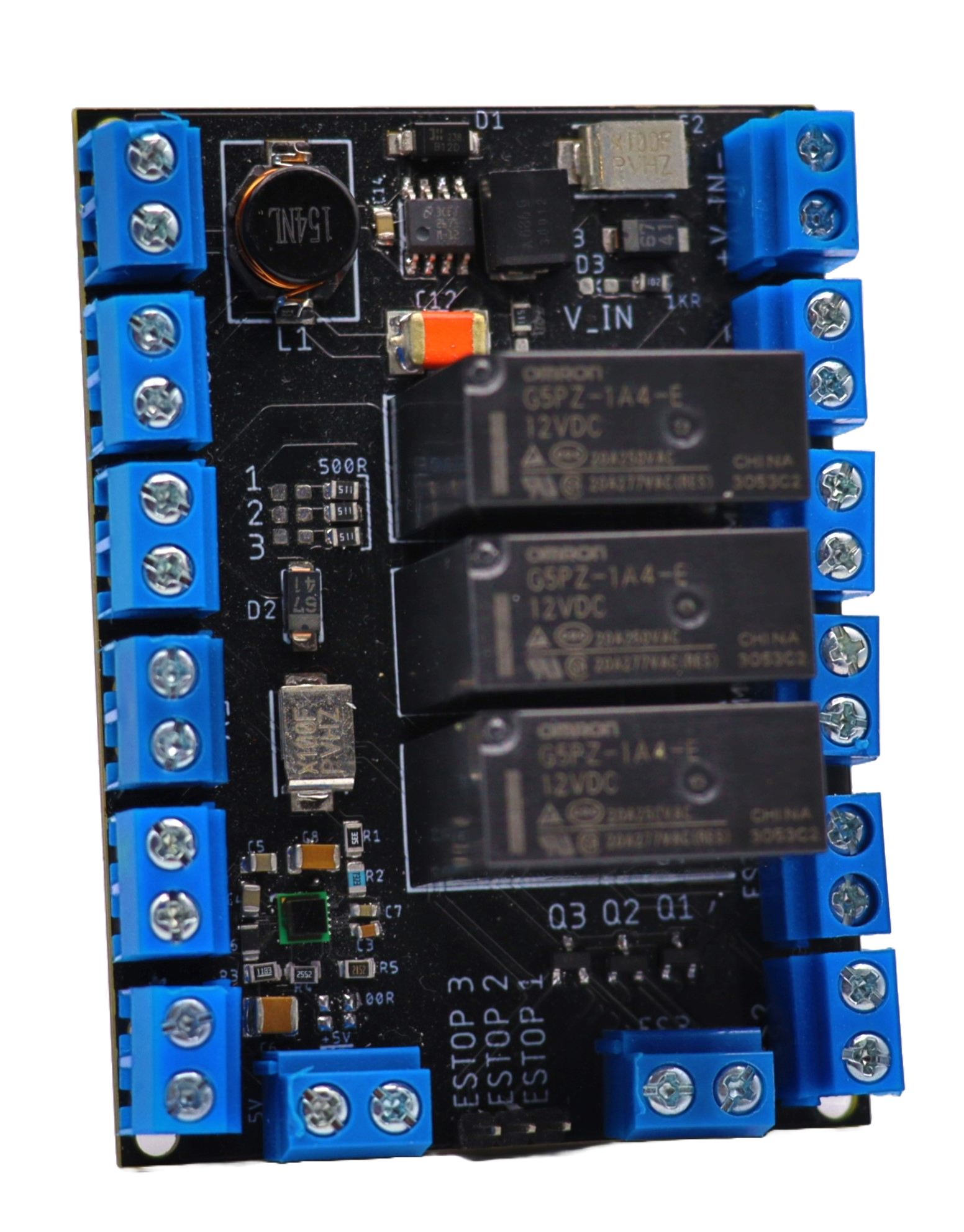
Power Board
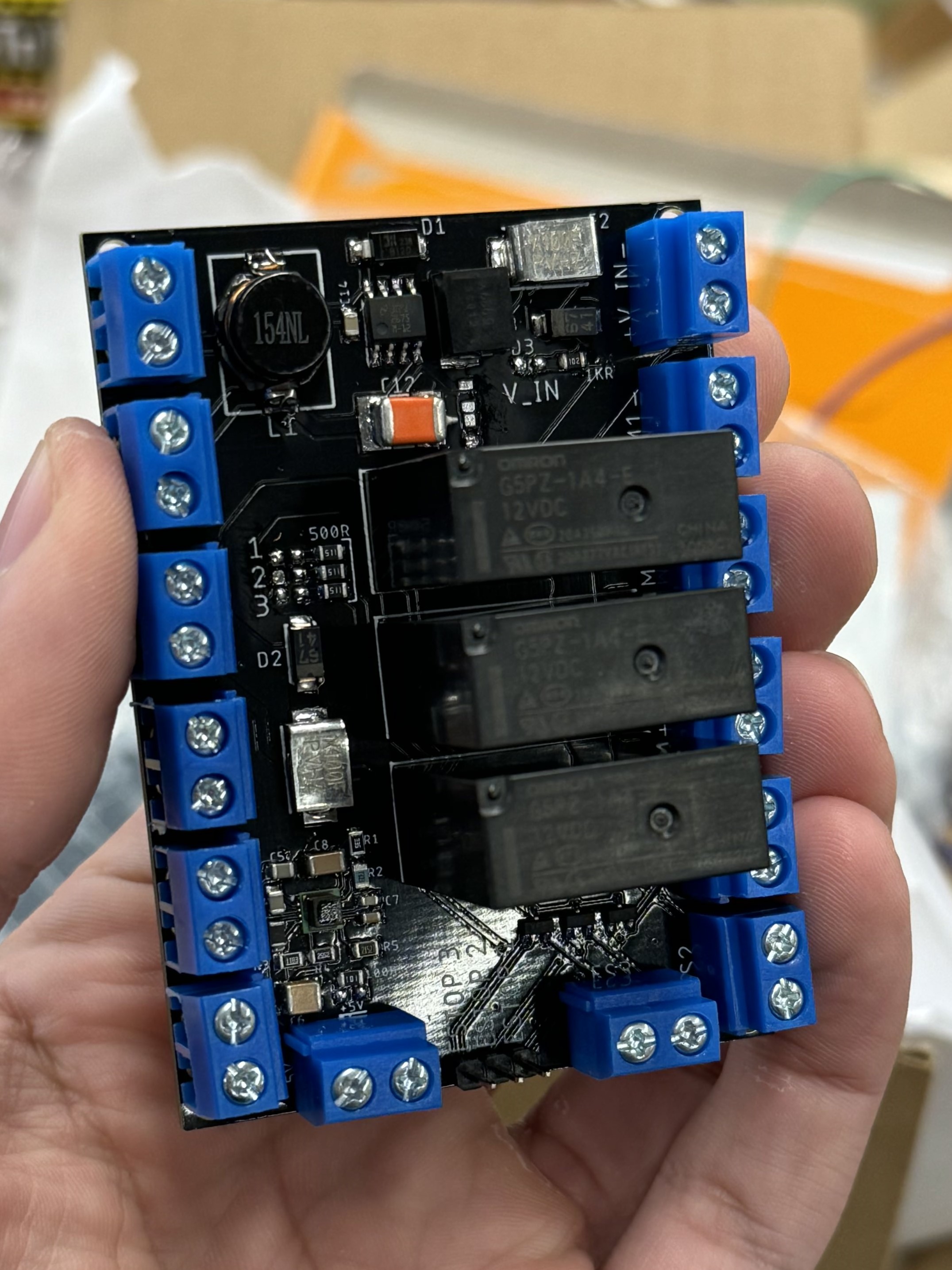
Soldered Power Board
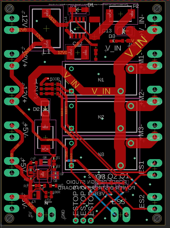
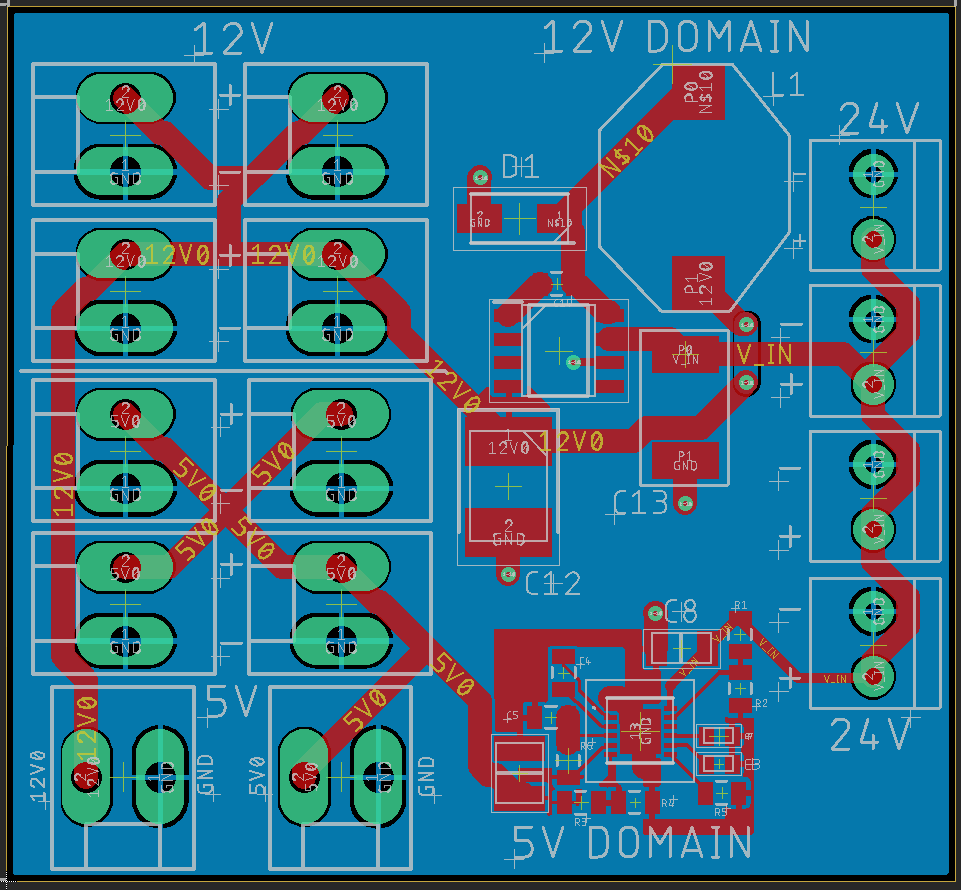
Power Board Layout (Ground Planes Not Pictured)
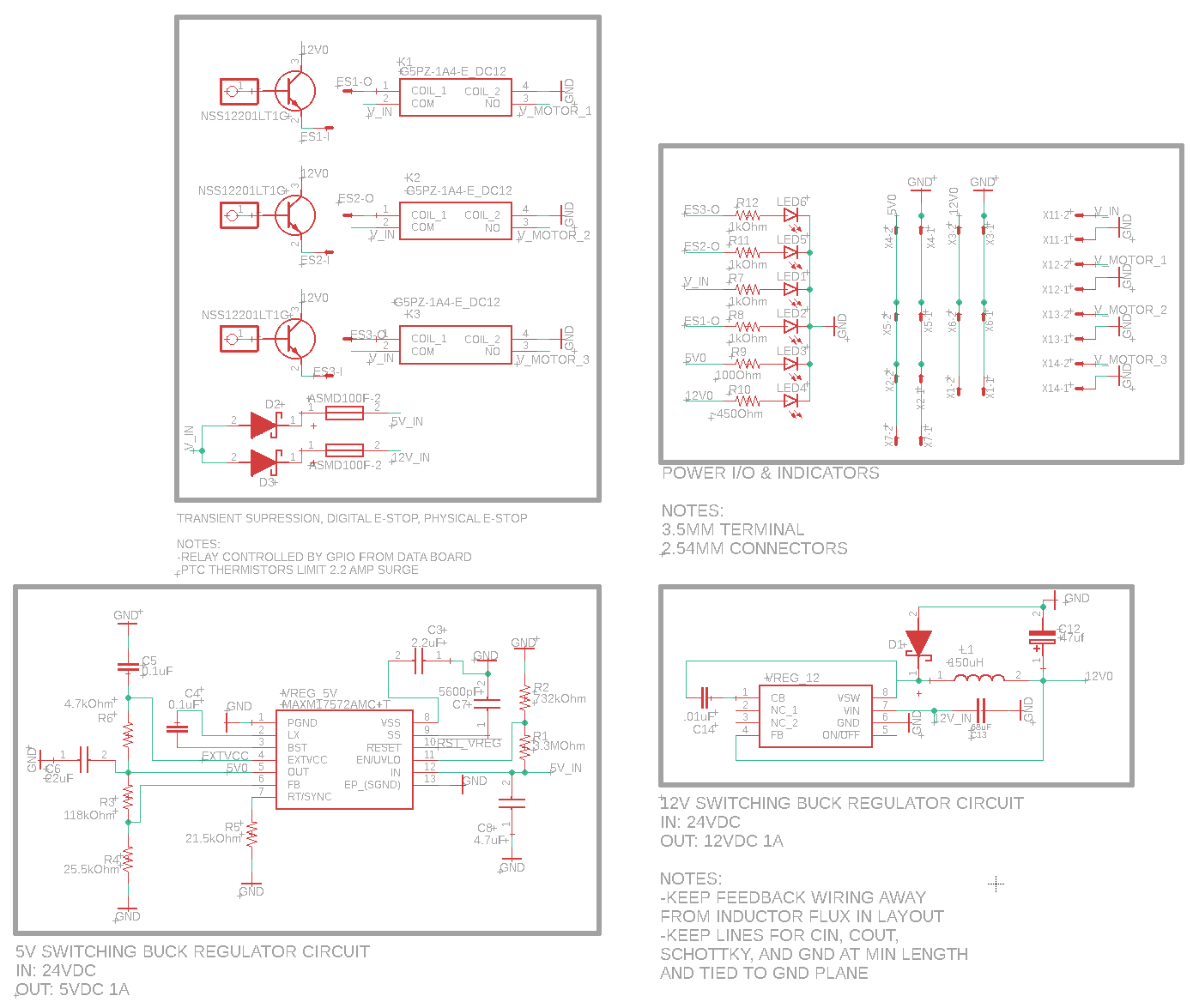
Power Board Schematic Capture
- Supplies all system motors with a maximum continuous power of 72 Watts, with an estimated peak of ~200 Watts (at 24VDC)
- Provides stable power to all motor controllers, sensors, and microprocessors at 3.3V, 5V, and 12V
- Ensures operator and system safety with passive shutdown
- Ensures safe power delivery by incorporating protection mechanisms such as overcurrent and reverse polarity protection.
- Power Integrity Ground-plane is used minimally to maximize current return path. Filtering passives are properly selected based on present frequencies and vias are kept short. Signals on different planes cross orthogonally
- Ample Connectivity: Screw terminals and shrouded XT-60 connectors allow for easy connectivity during set-up and debugging.
- Robust Component Selection Switching regulation circuits are designed based off of manufacturer guidelines. Regulator circuits are designed to mitigate input voltage spikes with a factor of safety of 2.5
- Easy Assembly: Common, cheap passive components are used. The boards silkscreen lists each component which can be referenced in the BOM. The board can be easily assembled via reflow with the use of a stencil.
- Safety & Reliability: Operator and system are protected from many common threats with the inclusion of passive safety systems (see 'Threats' table below).
- Real-Time Indicators: RGB LEDs display system status, such as communication errors or operational readiness.
- Functions:
- Design Features:
- Circuit Subsystems:
- 24 Volt Domain: Input supply voltage to board. Routed to both regulator circuits as well as through electronic E-Stops to power motors & motor controllers
- 12 Volt Buck Regulator: Designed to provide stable power to medium-power subsystems, such as the motor controller shielded CAN network. It utilizes a Texas Instruments switching buck regulator to handle an input voltages range of 4.5V to 60V, ensuring a smooth and denoised output of up to 1A suitable for operation-critical components
- 5 Volt Buck Regulator: Supplies low-voltage power to sensors, microcontroller, and encoders. It employs an Analog Devices/Maxim Integrated switching buck regulator to regulate an input voltages range of 4.5V to 60V with a maximum output of 1A, catering to sensitive and low-power electronic peripherals.
- Digital E-Stop System: Controlled by I/O pins from the Data board, 3 transistors manage SPST Form A E-Stop Relays. Power to the motors can instantly be cut-off if the microcontrollers detect that the operator's or system's safety is in jeopardy.
- Use Indicators: LEDs indicate the operating state of each circuit to provide real-time feedback.
| Physical Characteristic | Value |
|---|---|
| Layers | 2 |
| Dimensions | 75mm × 55mm |
| Thickness | 1.6mm |
| Copper Thickness | 4 Oz./ft2 |
| Substrate | FR-4 |
| Track Spacing | 13 mil |
| Vias | Tented, 0.3mm |
| Threat | Mitigation Feature |
|---|---|
| Current Surge | PPTC Thermistors |
| Reverse Polarity | Reverse Polarity Diodes & Shrouded Connectors |
| Supply Fault | Form A Relays |
| MCU Disconnect | Form A Relays |
| Back-EMF | Shrouded Motor Controller |
Prototype vs. Final Design
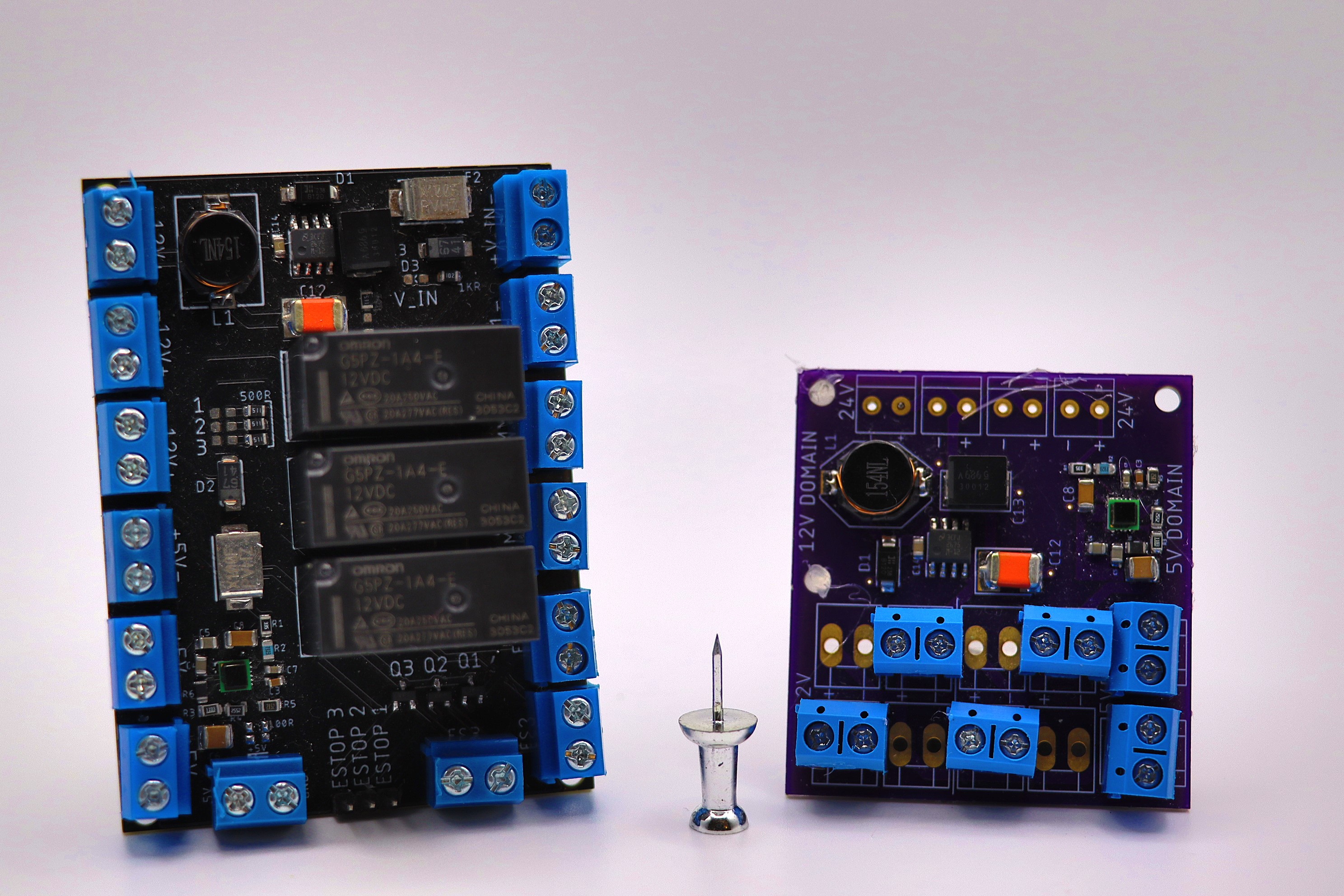
Final Design vs. Prototype
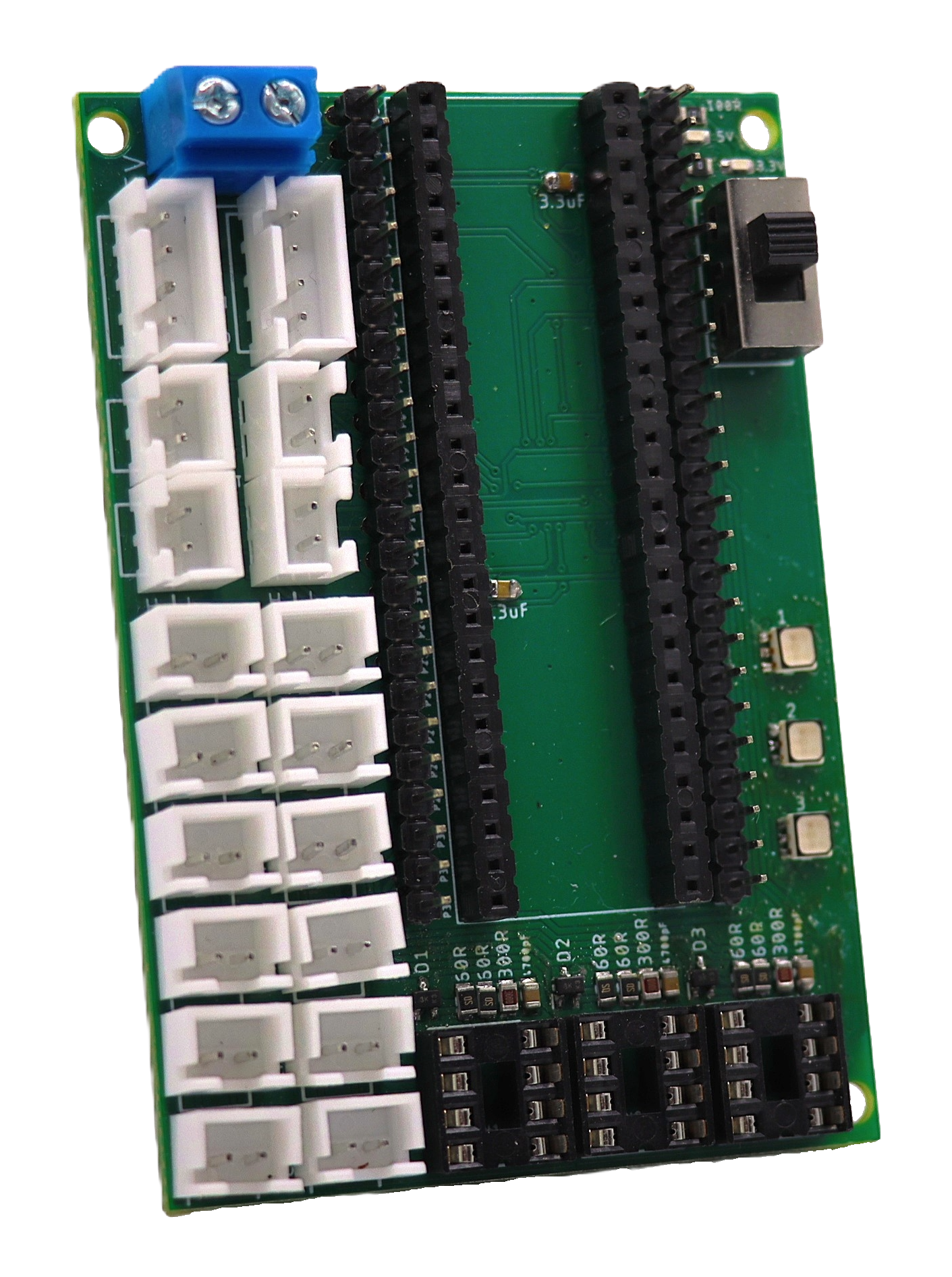
Data Board
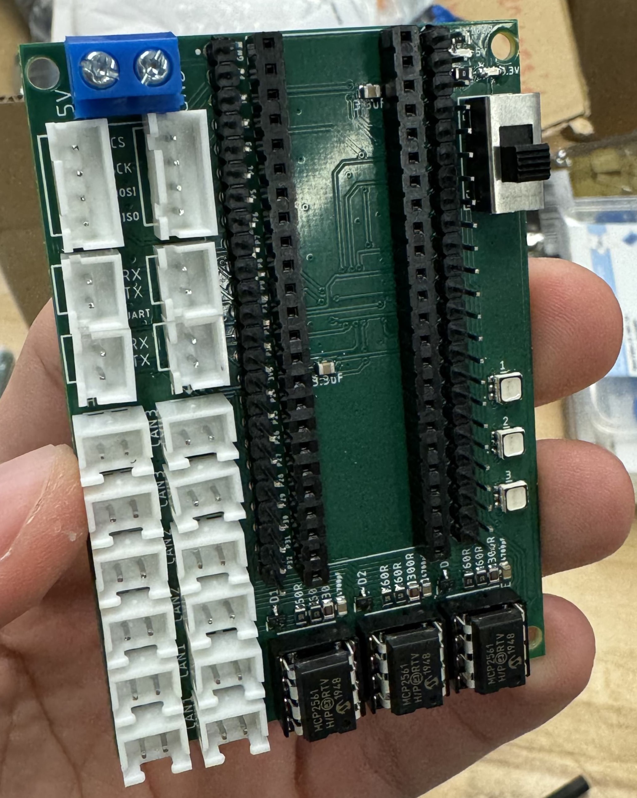
Soldered Board
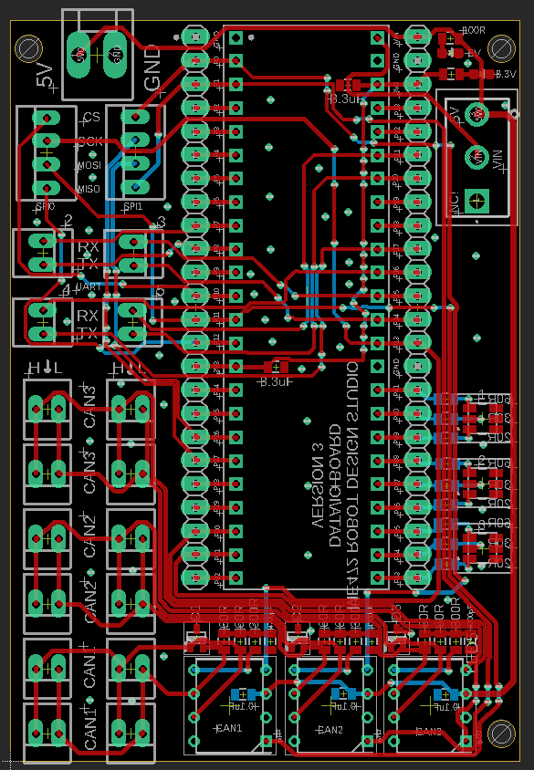
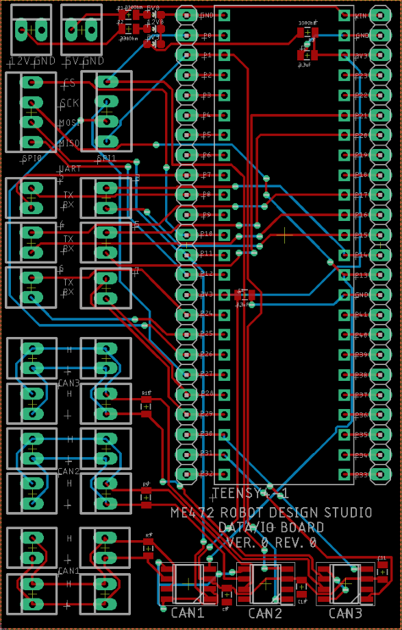
Board Layout (Ground Planes Not Pictured)
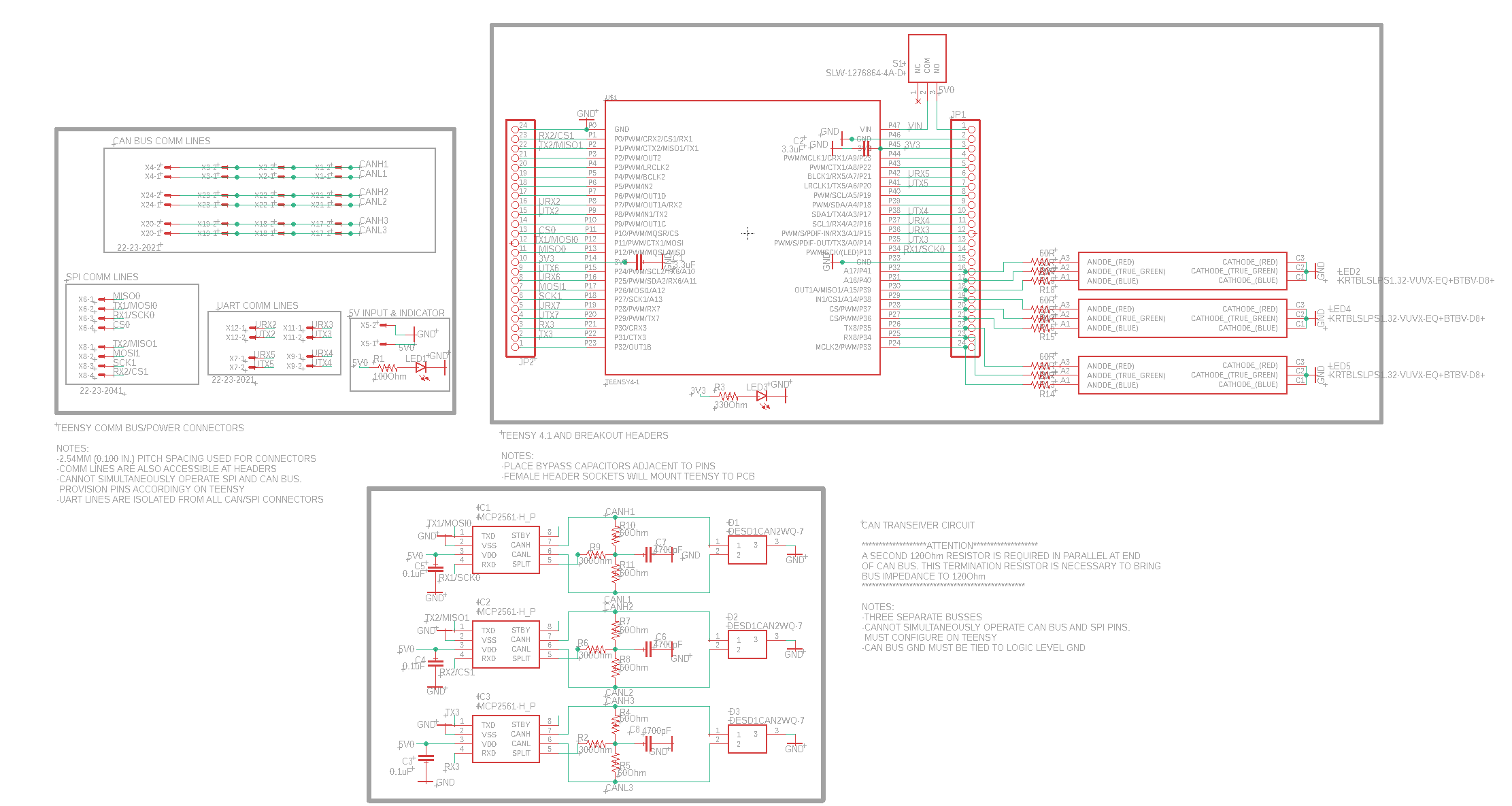
Electrical Schematic
- Provides 2 SPI ports, 4 UART ports, and 3 CAN busses for connection to the microcontroller to support multiple types of peripherals
- Directly commands subsystems motor controllers
- Communicates between subsystems too coordinate movement between all 4 devices via an external CAN Bus
- Controls activation of each motor E-Stop by direct interface with NPN BJT's on the power board
- Connects Teensy Microcontroller to peripheral sensors and encoders
- Displays system state with 3 RGB LED's
- Provides 2 SPI, 4 UART, and 3 CAN connections to the microcontroller to support multiple types of peripherals
- Expansion Support: Contains a surplus of I/O ports so that different peripherals & components can be added in future
- Signal Integrity: Controlled impedance routing for high-speed signals, ground plane is minimally interrupted, stitching vias exist throughout the board to guarantee low-impedance return path
- Filtering: Bypass Capacitors at various power and GPIO pins act as Low Pass filters for the MCU
- High Reparability: Teensy and CAN transceivers, the two most probable chips to burn out, are implemented in socket (P-DIP) packages for easy replacement.
- Easy Debugging: Onboard LEDs indicate CAN activity, Teensy Microcontroller is broken-out into headers for testing and scoping, and an onboard toggle switch allows for easy power cycling
- Compact Layout: Optimized for minimal space without sacrificing functionality
- Functions:
- Design Features:
| Physical Characteristic | Value |
|---|---|
| Layers | 2 |
| Dimensions | 80mm × 55mm |
| Thickness | 1.6mm |
| Copper Thickness | 1 Oz./ft2 |
| Substrate | FR-4 |
| Minimum Track Spacing | 6 mil |
| Vias | Tented, 0.3mm |
| Threat | Mitigation Feature |
|---|---|
| Signal Noise | Decoupling Capacitors |
| Voltage Spikes | Transient Voltage Suppressors |
| Data Corruption | Parity Check and Error Correction Protocols |
Prototype vs. Final Design

Encoder Boards
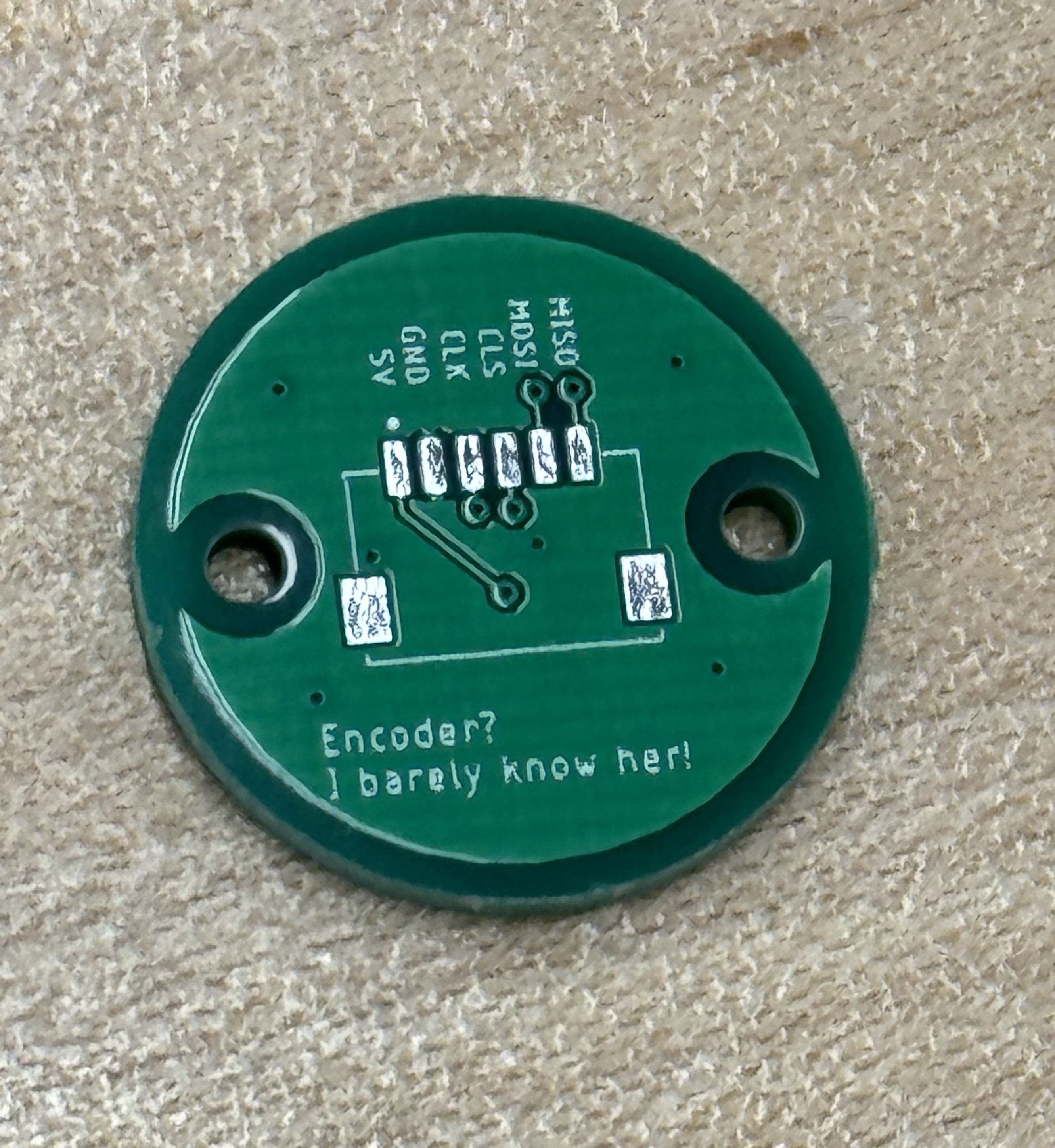
Bare Encoder Board
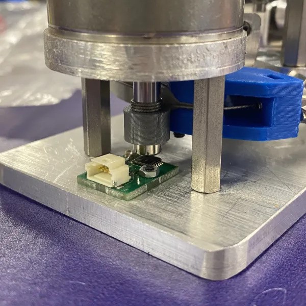
Soldered Board Mounted to Haptic Thumb
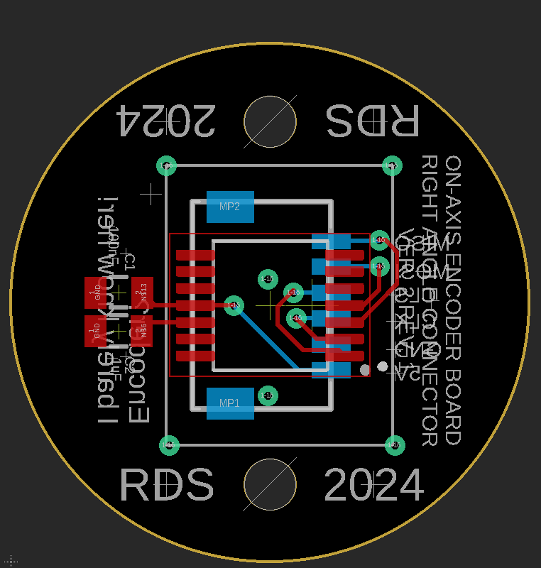
Board Layout (Ground Planes Not Pictured)
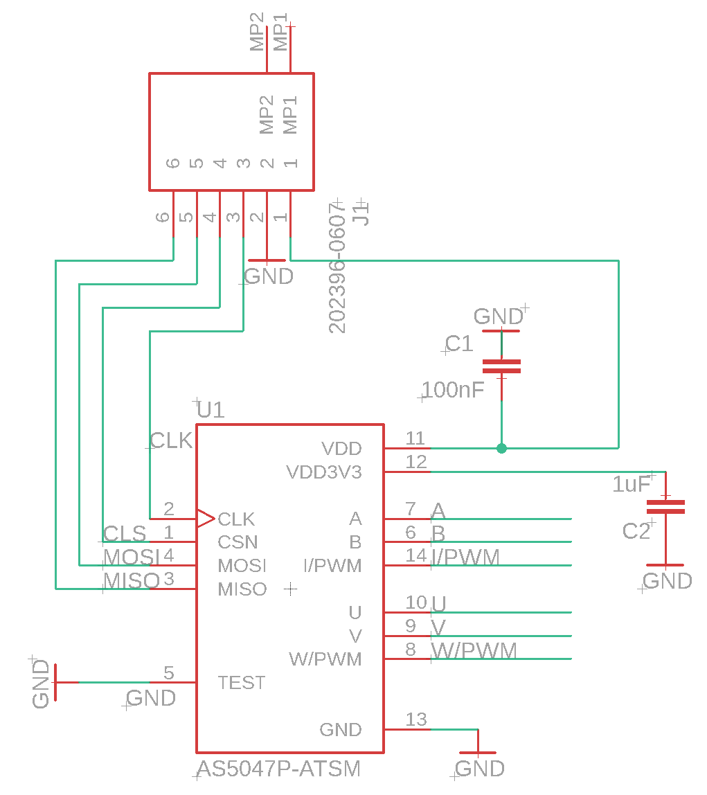
Electrical Schematic
-
Function:
- The encoder board uses high resolution 14 bit hall-effect rotary encoders to measure shaft positions providing feedback via SPI to the MCU and motor controller. Four different versions of this board were designed in order to satisfy each subteam's sizing and mounting constraints. Each of the four boards is of a very small form factor, also the layout and circuit of each is identical.
-
Design Features:
- Custom Dimensions Custom dimensions, layout, and connector configuration tailored to each subsystem
- High Precision: Supports 14 bit resolution, or 0.022°
- Low Profile: Designed to fit within compact mechanical systems
- High Speed: Supports SPI clock rates up to 10MHz
- No Shielding required: Encoder is immune to external stray fields
| Physical Characteristic | Value |
|---|---|
| Layers | 2 |
| Dimensions | 15mm r. |
| Thickness | 1.6mm |
| Copper Thickness | 1 Oz./ft2 |
| Substrate | FR-4 |
| Track Spacing | 3 mil |
| Vias | Tented, 0.3mm |
| Threat | Mitigation Feature |
|---|---|
| Signal Degradation | Filtering Capacitors |
| Bad Connection | Latching Molex Pico Connectors |
Bill of Materials
Mechanical System Overview
Robot Finger
The robot finger subsystem is engineered to closely replicate human finger curling motions, featuring two actively actuated joints that deliver smooth, natural articulation. Rather than relying on a traditional gear train, it uses a pulley-driven transmission with a 4:1 ratio at each joint, enhancing torque delivery while maintaining a compact profile. High-performance Maxon EC 45 flat motors supply the requisite torque density without adding bulk. To ensure stability under load, stainless steel cables are tensioned using simple screws and nuts, and magnetic encoders provide precise positional data for fine-tuned control. Structural components are fabricated through both water jet cutting and CNC milling for accuracy and durability. While performance and torque efficiency meet design goals, refining linkage interfaces and streamlining the assembly process remains an ongoing priority.
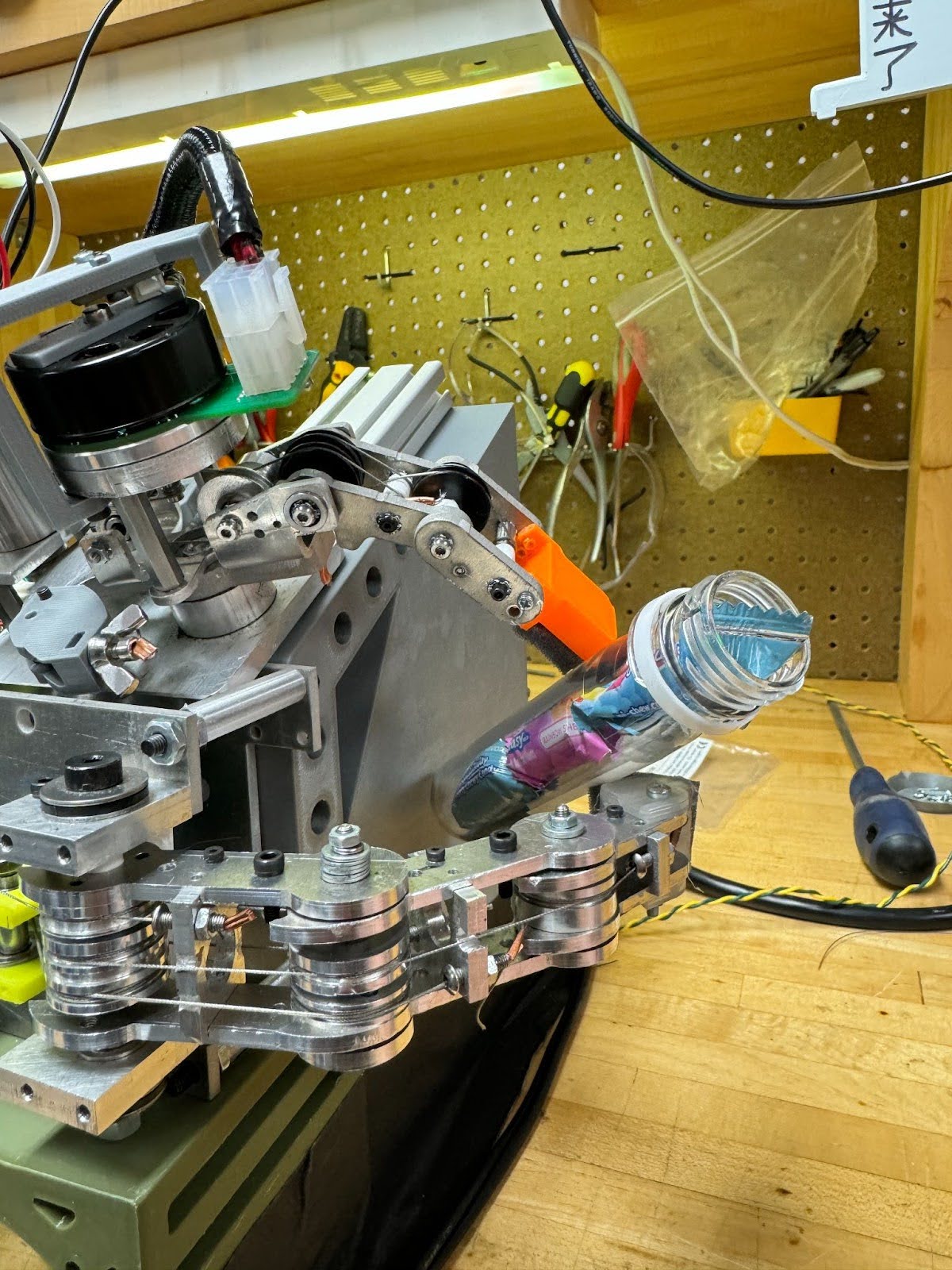
Robot Thumb
Similar to the robot finger, the robot thumb is tailored to replicate the dexterity and form factor of the human thumb, offering two actuated degrees of freedom to produce both 'waggle' (abduction/adduction: motion
that moves the thumb away from the palm) and 'curl'
(flexion/extension: curling or extending your thumb) motions. The 'waggle' joint operates at a 7.33:1 transmission ratio, driven by Maxon ECX Torque 22XL motors for steady, responsive motion. In contrast, the 'curl'
movement uses a 7.94:1 ratio powered by Maxon EC 45 Flat motors, chosen for their compact design and strong torque-to-size ratio. Multiple cable wraps, tensioning blocks, and
CNC-machined pulleys work together to maintain tension. High-precision machining, including turning and milling, ensures tight tolerances and
secure mechanical coupling. Similar to the finger, there are still some issues regarding tensioning which would likely be resolved by refining the pulley system and having an easier method for tensioning.
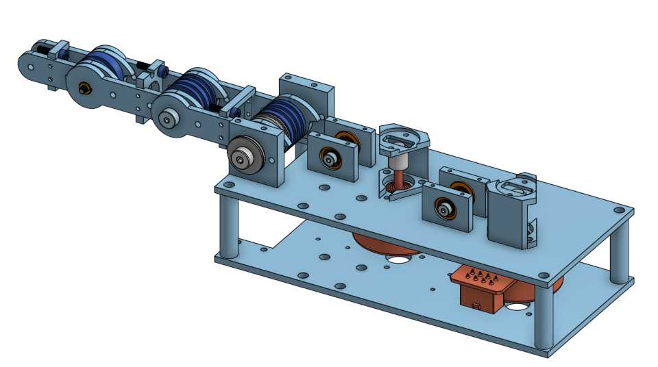
Haptic Finger
The haptic finger subsystem recreates human finger dynamics, offering two actively controlled joints (MCP and PIP) plus an additional passive degree of freedom for
a more natural range of motion. Stainless steel cables, routed through machined pulleys, maintain precise motion transfer. Cables are tensioned using vented screws
and wing nuts, allowing convenient adjustments and steady performance over time. Similar to other designs Maxon ECX Torque 22XL motors drive the system and are mounted near the palm.
The motors are placed in such a way that they do not interfere with the mounting of the haptic thumb.
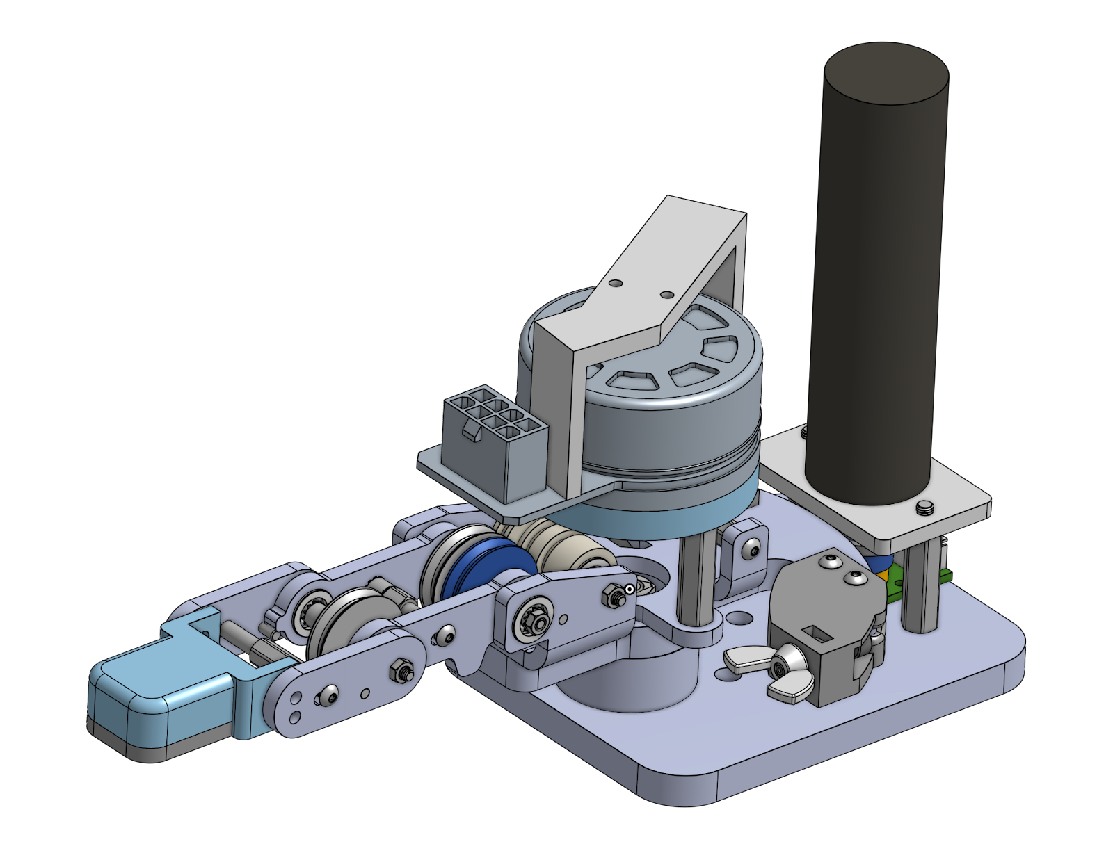
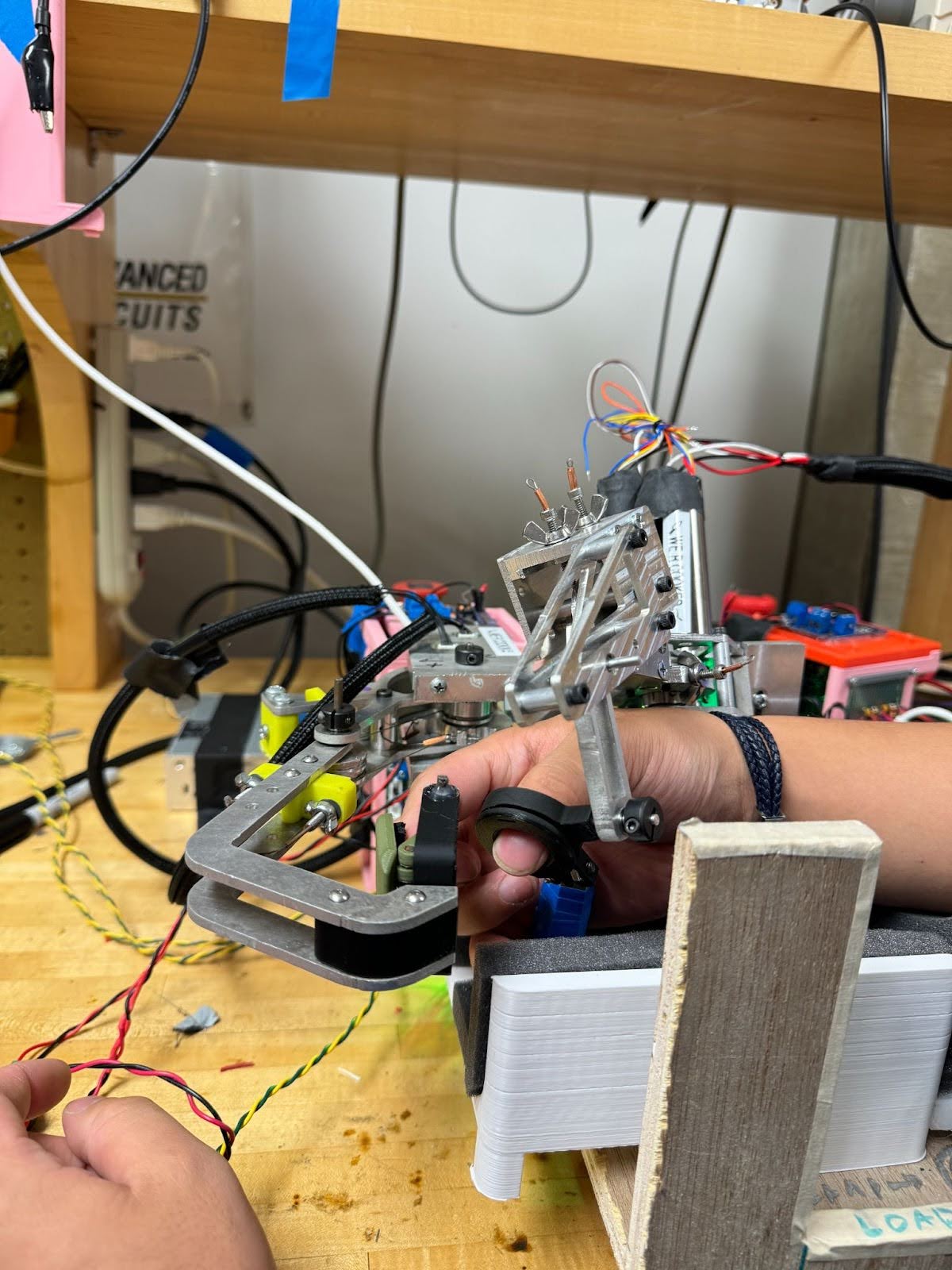
Haptic Thumb
The haptic thumb subsystem attempts to emulate the range of motion for the human thumb with only 2 driven degrees of freedom. Similar to the robot thumb it offers 'waggle' and 'curl' motions enhanced by an additional passive degree of freedom. Cable
tension is managed via a series of idler pulleys and vented fasteners to achieve smooth, consistent engagement. Maxon ECX motors drive the both the 'waggle' and 'curl' motions, and a rotating
fitting allows your thumb to freely swivel within the mechanism. A flexible TPU thimble interface accommodates various thumb sizes while preserving a
secure, ergonomic fit. CNC-machined elements support a sturdy yet lightweight structure. Friction in the cable system occasionally emerges during operation, but we believe this issue could
be fixed with higher tolerance pulleys, and a less complex way to tension the cables.
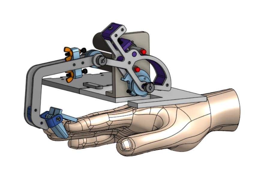
Mechanical System: Haptic Thumb

Haptic Thumb Mechanism CAD
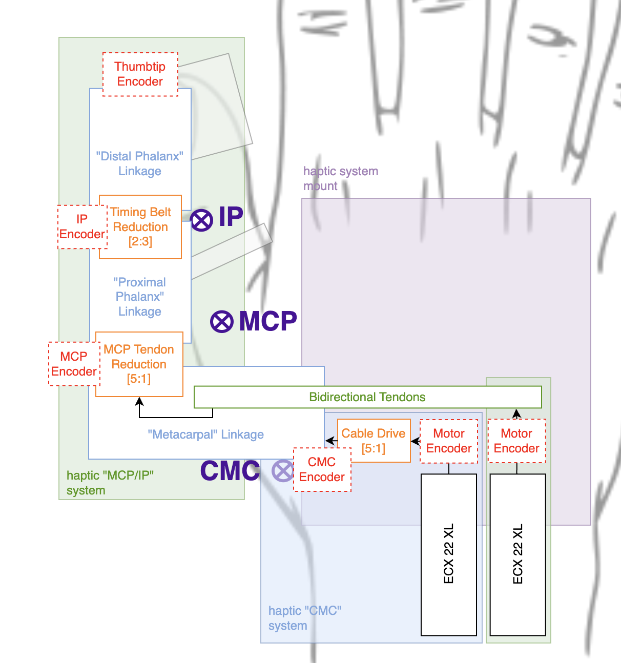
Mechanical System Block Diagram
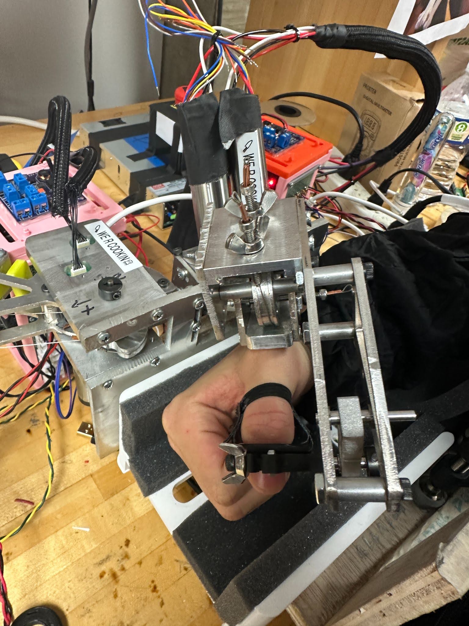
Haptic Thumb Mechanism in Use
Haptic Thumb Overview
The goal of the haptic thumb system (pictured above) was to create a haptic interface for the robotic thumb with two actuated degrees of freedom while providing a comfortable workspace for the user’s thumb. Given this constraint, we broke down the thumb motion into two principal functional motions that we defined ourselves: CMC planar rotation ‘waggling’ of the thumb and MCP/IP 'curling'. These two degrees of freedom make up two subsystems of our design as well as a third subsystem consisting of the thimble holster interface to the user’s thumb. The MCP/IP subsystem and the thimble subsystem each contain an unactuated passive degrees of freedom to provide greater comfort to the user during our curl motion. The mechanical system block diagram above depicts the subsystems and their major components and the decomposed motions are also depicted in the figure below
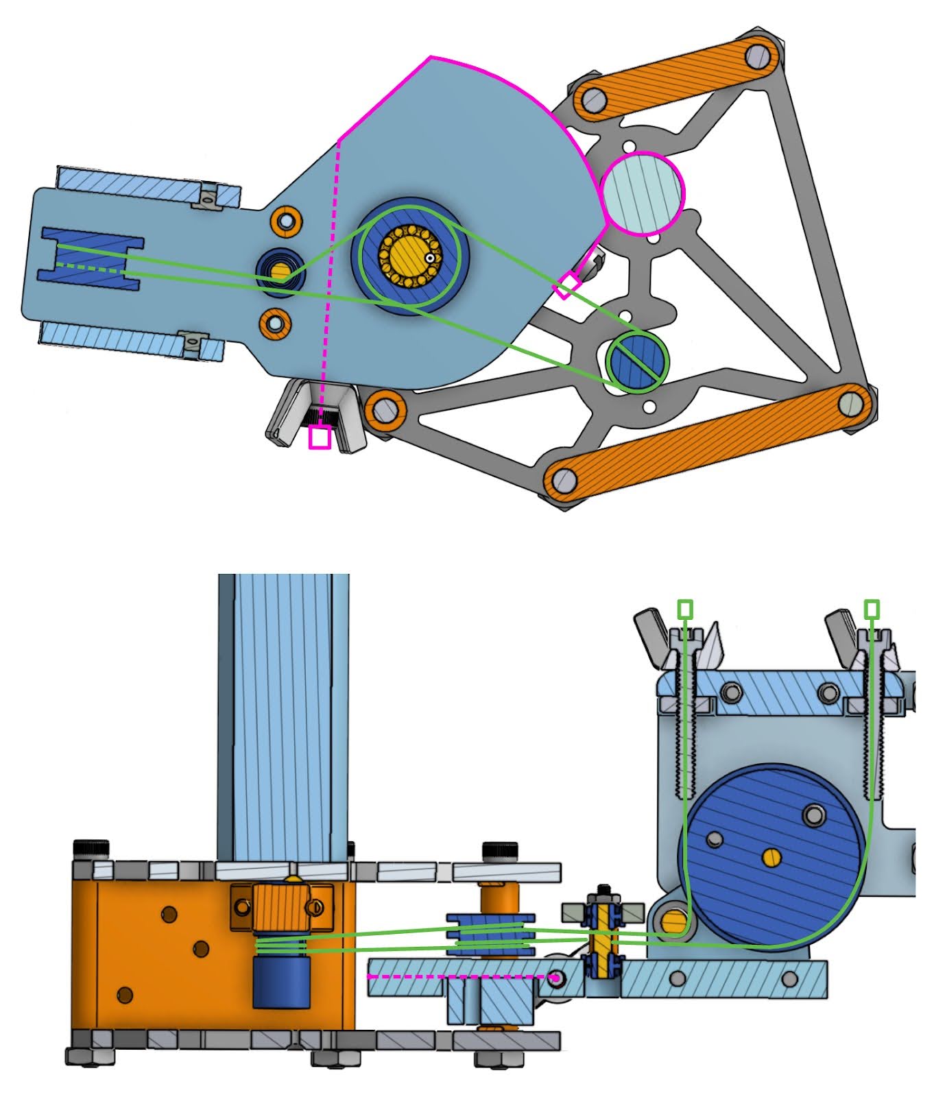
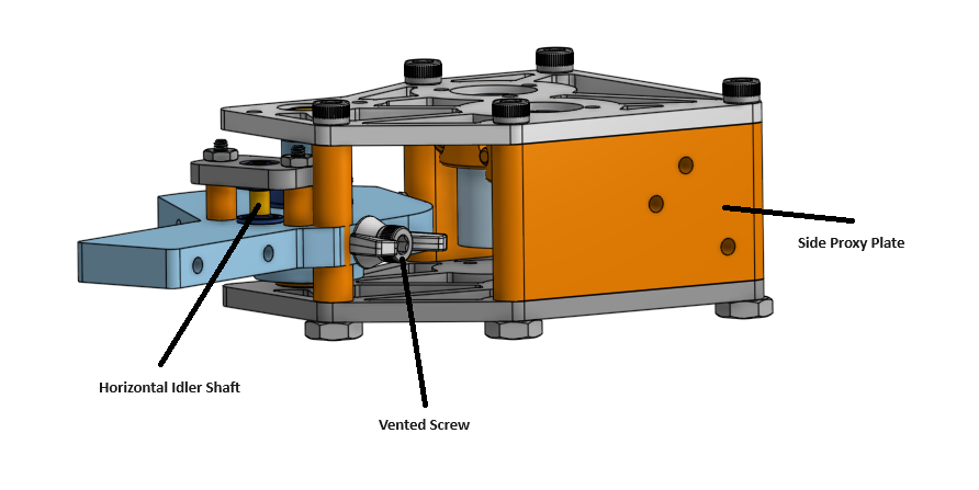
Cable Routing
The haptic thumb system makes use of three vented screws to tension the cables: one in the CMC subsystem and two in the MCP/IP subsystem. The configuration shown
below creates a 1.4:1 coupling
The CMC cable is wrapped around the CMC Motor Pulley 3 times and is terminated through a wire-lockable screw at one end of the system. The other side of the cable
is wired through the CMC plate (illustrated by the dashed pink line below) and is then wired through a vented screw and terminated with a copper crimp. The cable
is tensioned off of the MC plate by unscrewing the vented screw in the counterclockwise direction against a wingnut.
The MCP/IP cable is wrapped around the MCP/IP Motor Pulley 3 times, traversing through a drilled hole in the center of the pulley, and is wired across the CMC system
through the use of 3 idler pulleys/shafts. The CMC idler pulley sits on the CMC shaft and allows the motor pulley to be remotized to the same location as the CMC
motor pulley. This pulley has 2 grooves that allow for 1 wrap in each direction. The horizontal idler shaft is located between the CMC idler and the vertical
idler shaft and guides one side of the cable to the location of the MCP/IP pulley, allowing the cable to approach the pulley perpendicularly to its surface.
The vertical idler shaft is located between the horizontal idler shaft and the MCP/IP pulley, and guides one side of the cable towards the MCP/IP surface in a way
that allows it to wrap tangentially in both directions. The cable is terminated at each end using copper crimps with a vented screw and wingnut that create tension
in the cable by rotating in the counterclockwise direction off of a tensioning block and a hex nut underneath to lock the configuration.
Cable Routing
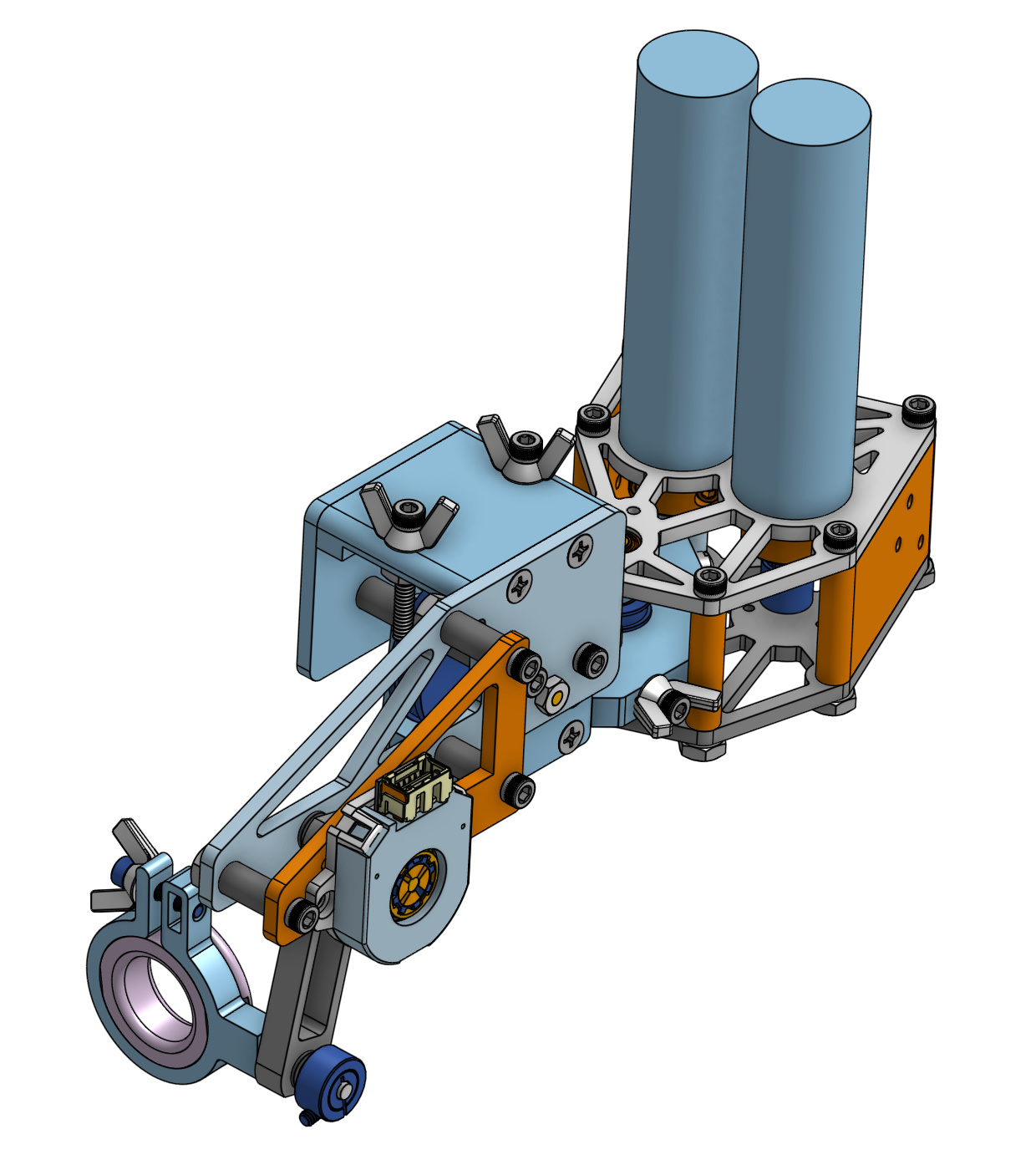
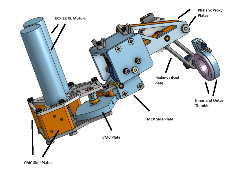
CAD Model
The full CAD model of the haptic thumb system is shown below The motors and connection points between the different subsystems are outlined. The CMC Side Plates provide
a mounting point for the haptic thumb system to connect to the rest of the haptic system. The MCP Side Plates are attached to the CMC Plate to connect the CMC and MCP/IP
systems together. The Phalanx Proximal Plates connect to the compliant Phalanx Distal Plate to connect the Thimble system to the rest of the haptic system. The Inner and
Outer Thimble connect the user to the haptic system. Different views of the subsystems are shown below to highlight the different parts and features.
All bearings within the system are designed to be push fit with both the plates and the shafts. All plates should be manufactured using CNC milling and reaming, and
shafts/pulleys were turned on the manual lathe. All components were designed to be made out of metal, with the exception of the inner thimble, which is designed to
be made out of 3D printed TPU.
Haptic Thumb CAD Model
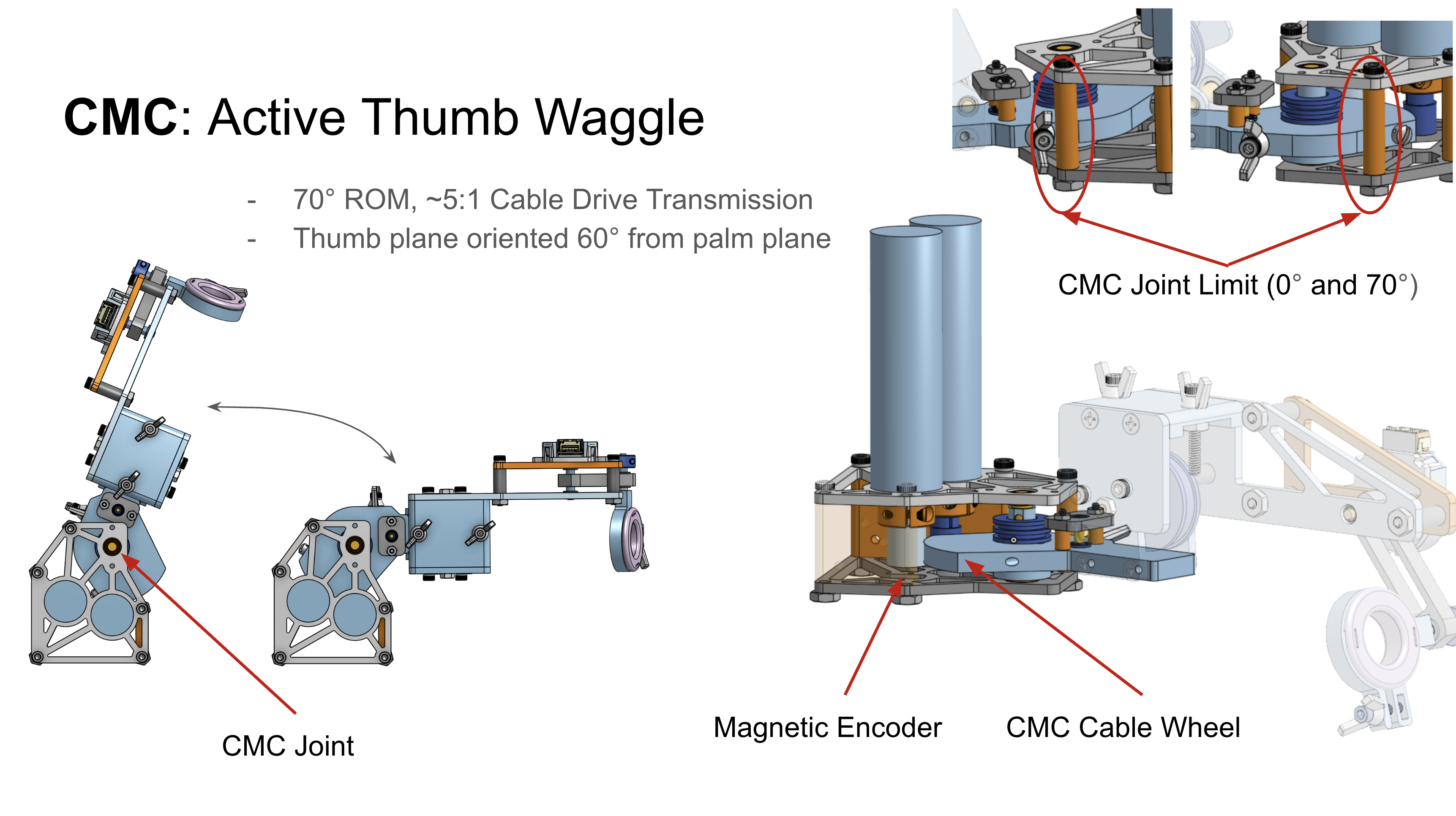
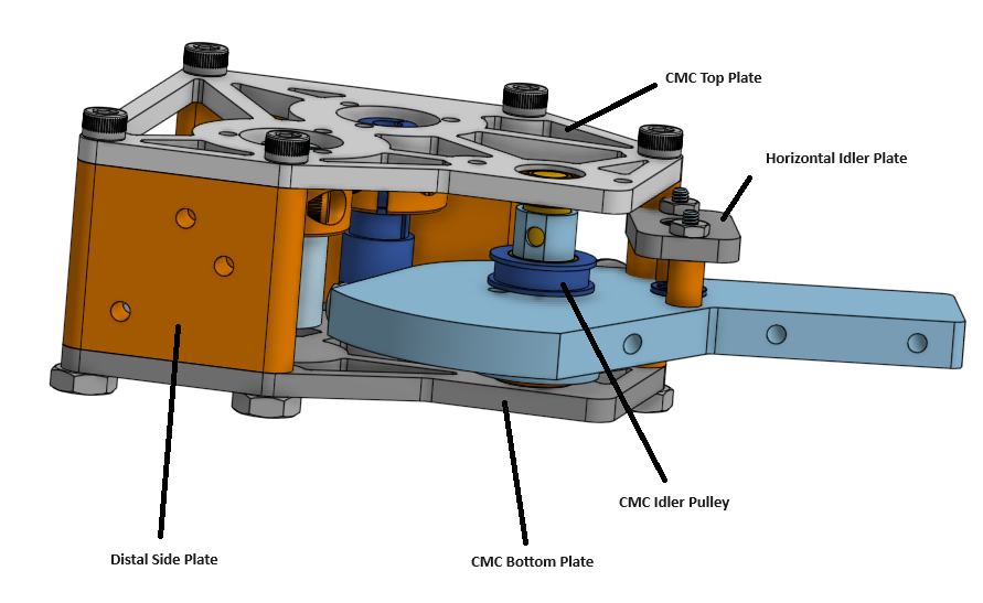
CMC Subsystem
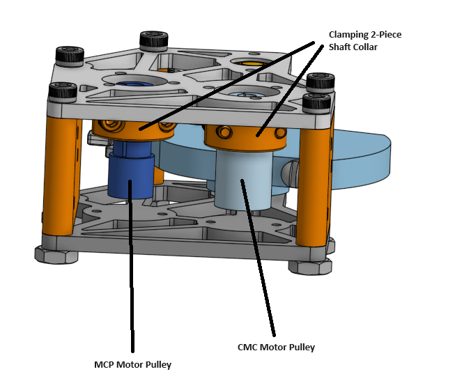
The CMC subsystem is depicted below, with joint limits set at 0° and 70° by a spacer separating the top and bottom plates. This subsystem utilizes a ~5:1 cable drive
transmission ratio, determined by the radii of the CMC plate and CMC motor pulley.
The assembly process begins with the top plate sub-assembly, which includes the CMC top plate, ECX 22 XL motors, 2-piece collar shafts, and motor pulleys. These components
are assembled together to ensure alignment and secure attachment. Next, the CMC plate is assembled with the bottom plate, incorporating the CMC shaft and idler pulley.
This step may require a clamp or a second set of hands to maintain alignment. At this point, the cable routing for the CMC is performed. The CMC cable is wrapped around
the CMC motor pulley three times, terminated through a wire-lockable screw, and routed through the CMC plate, vented screw, and copper crimp. Once the cable is properly
tensioned, the spacers between the top and bottom plates can be added. Finally, the horizontal idler shaft is installed on the CMC plate, completing the mechanical assembly
of the CMC subsystem.
CMC Subsystem
CMC Subsystem
CMC Subsystem
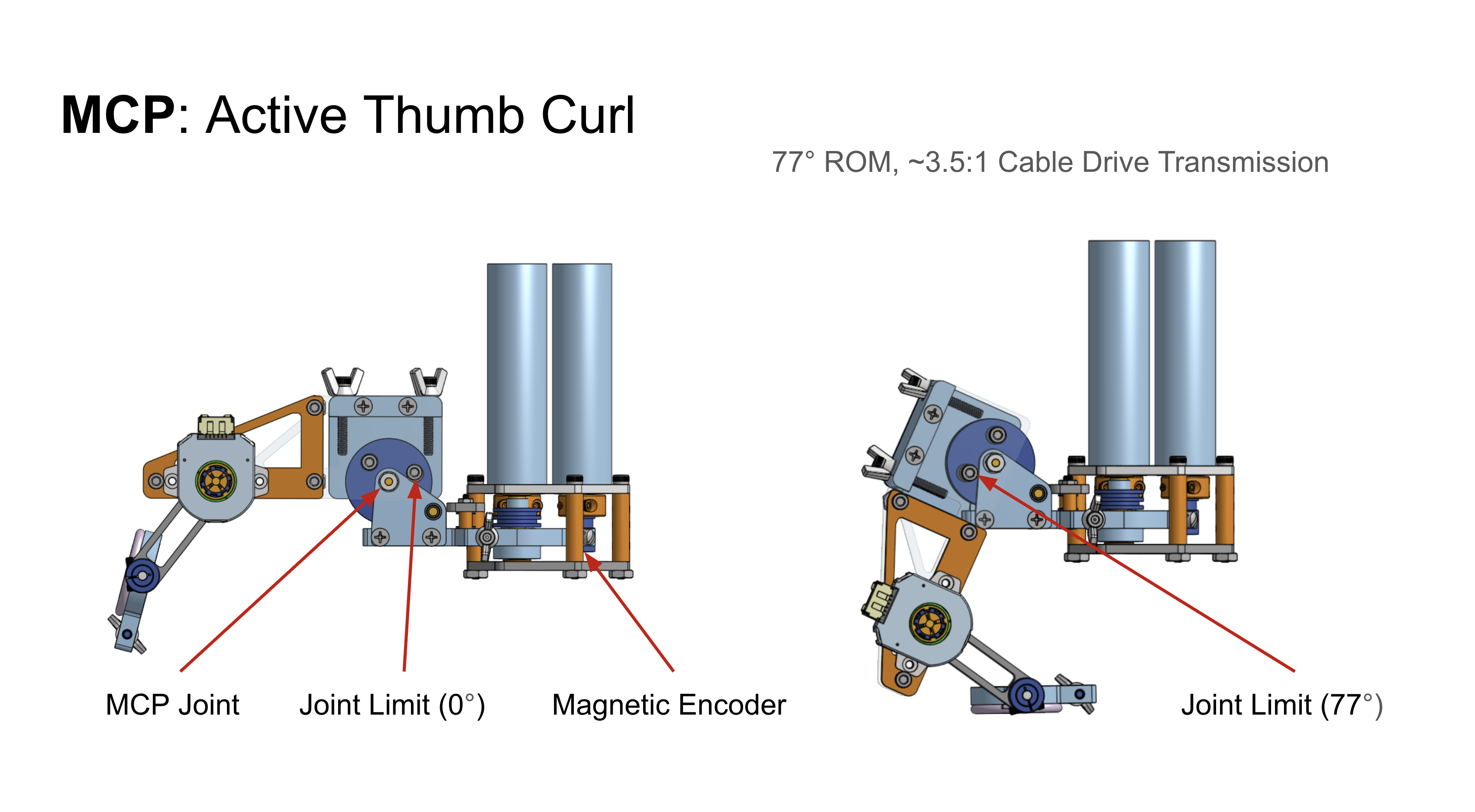
MCP/IP Subsystem
The components of the MCP/IP subsystem are depicted below The active MCP joint is driven at a 3.5:1 transmission ratio due to the diameter of the MCP pulley and two sets of
spacers contact the edge of the MCP side plates to create the mechanical joint limits providing 77 degrees of rotational motion. The MCP pulley is clearance fit on the MCP
shaft and loctite was used to constrain the pulley rotation to the shaft rotation. As a result, the pulley as well as all of the proximal phalanx plates rotate together.
This subsystem can be assembled separately from the CMC subsystem and attached at a later time, meaning that the CMC joint does not need to be re-tensioned if repairs or
adjustments need to be made to the MCP/IP subsystem.
Assembly for this subsystem involves locating all of the components (spacers, bearings, and plates) on the MCP shaft with the exception of the phalanx proximal plates. At
the same time, the vertical idler shaft needs to be located within the bearings in the MCP side plates. Once the inner MCP pulley joint has been assembled, the outer phalanx
prox and phalanx prox L plates can be attached to the MCP shaft. The shaft and plates for the passive IP joint can be assembled before or after the assembly of the MCP.
Thimble
The thimble subsystem is designed to provide comfortable but secure attachment between the user’s thumb tip and the haptic system. In order to accommodate multiple thumb sizes, multiple diameters of the thumb tip were printed out of TPU, a flexible polymer that allows for a more comfortable experience. The inner thimble piece can be easily removed and swapped for a different size by unscrewing the bolt that clamps the inner thimble. Multiple iterations of the thimble design were created, including a version that uses an elastic band that wraps around the proximal phalanx of the user’s thumb to secure the thimble on the thumb. Further testing is needed to determine whether the flexibility of TPU is sufficient to prevent slippage or if a more robust thumb attachment strategy is required. Additionally, the system lacks the roll degree of freedom for the thumb tip, which results in a moment around the thumb that could be potentially uncomfortable. Designing and implementing a lightweight but secure roll degree of freedom should be a focus in future iterations.